NV1 PGRAPH: graphics engine
Contents
Introduction
The NV1 includes the first generation of the 2d/3d graphics engine. It is capable of performing the following operations:
- Solid: drawing solid-colored points, lines, triangles, and rectangles;
- Blit: copying rectangular areas inside a buffer, or between buffers;
- Image from CPU: drawing a rectangular image with pixel data uploaded through the command stream;
- Bitmap from CPU: drawing a 2-color bitmap with bitmap data uploaded through the command stream;
- Image from memory: drawing a rectangular image with pixel data read from a DMA object;
- Image to memory: downloading a rectangular area from the render buffer to a DMA object;
- Textured quad: drawing a textured linear- or quadratic-interpolated quad with texture data uploaded through the command stream, possibly with per-vertex lighting.
- Notification: writing a simple 16-byte structure indicating completion of commands so far to a DMA object.
Every drawing operation (that is, all of the above except image to memory) can be used together with the following operations:
- clipping to a rectangular area,
- per-bitplane write masking,
- color keying,
- one of:
- blending using the alpha component, or a separate blend factor (aka BETA),
- bitwise operations using the source color, the destination color, and a 64×1, 1×64, or 8×8 repeating 2-color bitmap pattern.
- color format conversion (with dithering) - the supported source formats are:
- R5G5B5 and A1R5G5B5,
- R8G8B8 and A8R8G8B8,
- R10G10B10 and A2R10G10B10,
- Y8 and A8Y8,
- Y16 and A16Y16 (though only high 10 bits of Y and 8 bits of A are actually used).
The graphics engine has access to one or two buffers in VRAM, managed by PFB. The supported formats include:
- 8bpp: indexed Y8,
- 16bpp direct color: D1R5G5B5 (where D is the “DAC LUT bypass” bit),
- 16bpp indexed: D1X7Y8,
- 32bpp direct color: D1X1R10G10B10,
- 32bpp indexed: D1X23Y8.
Classes, objects, and methods
The graphics engine is operated by submitting so-called methods (ie. commands). Methods are associated with objects and classes.
A class (ie. object type) is a grouping of related methods that can be used together to perform an operation - there is one class for every drawing operation that PGRAPH can perform (as listed above), plus a few classes setting global parameters that will be used by all drawing operations (so-called context objects). In addition to their main function, all classes can also be used to request a notification. The classes are identified by a 5-bit class id and include:
0x01:BETA: sets the blending factor,0x02:ROP: sets the global bitwise operation,0x03:CHROMA: sets the global color key,0x04:PLANE: sets the global plane mask,0x05:CLIP: sets the global clipping rectangle,0x06:PATTERN: sets the global pattern for bitwise operations,0x08:POINT: draws points,0x09:LINE: draws solid lines,0x0a:LIN: draws solid lins (ie. lines not including the final pixel),0x0b:TRI: draws solid triangles,0x0c:RECT: draws solid rectangles,0x0d:TEXLIN: draws textured quads with linear interpolation,0x0e:TEXQUAD: draws textured quads with quadratic interpolation,0x10:BLIT: performs blits,0x11:IFC: draws rectangular image from CPU,0x12:BITMAP: draws rectangular bitmap from CPU,0x13:IFM: draws rectangular image from memory,0x14:ITM: downloads rectangular image from framebuffer to memory,0x1d:TEXLINBETA: draws textured quads with linear interpolation and per-vertex lighting,0x1e:TEXQUADBETA: draws textured quads with quadratic interpolation and per-vertex lighting.
An object is a combination of a class and a set of options determining its mode of operation. Object options are a single 16-bit value arranged as follows:
- bits 0-4: OP - the drawing operation to be performed per-pixel:
- 0x00: RPOP_DS
- 0x01: ROP_SDD
- 0x02: ROP_DSD
- 0x03: ROP_SSD
- 0x04: ROP_DDS
- 0x05: ROP_SDS
- 0x06: ROP_DSS
- 0x07: ROP_SSS
- 0x08: ROP_SSS_ALT
- 0x09: ROP_PSS
- 0x0a: ROP_SPS
- 0x0b: ROP_PPS
- 0x0c: ROP_SSP
- 0x0d: ROP_PSP
- 0x0e: ROP_SPP
- 0x0f: RPOP_SP
- 0x10: ROP_DSP
- 0x11: ROP_SDP
- 0x12: ROP_DPS
- 0x13: ROP_PDS
- 0x14: ROP_SPD
- 0x15: ROP_PSD
- 0x17: SRCCOPY
- 0x18: BLEND_DS_AA
- 0x19: BLEND_DS_AB
- 0x1a: BLEND_DS_AIB
- 0x1b: BLEND_PS_B
- 0x1c: BLEND_PS_IB
- bit 5: CHROMA - if set, enables the color key
- bit 6: PLANE - if set, enables plane masking
- bit 7: CLIP - if set, enables clipping to the clipping rectangle
- bit 8: NOTIFY_VALID - if set, enables the NOTIFY method
- bits 9-12: COLOR_FORMAT_DST - a composite field that selects the source
color format and the destination buffer mask:
- 0: BUF0_A1R5G5B5
- 1: BUF0_A8R8G8B8
- 2: BUF0_A2R10G10B10
- 3: BUF0_A8Y8
- 4: BUF0_A16Y16
- 5: BUF1_A1R5G5B5
- 6: BUF1_A8R8G8B8
- 7: BUF1_A2R10G10B10
- 8: BUF1_A8Y8
- 9: BUF1_A16Y16
- 10: BUF01_A1R5G5B5
- 11: BUF01_A8R8G8B8
- 12: BUF01_A2R10G10B10
- 13: BUF01_A8Y8
- 14: BUF01_A16Y16
- 15: BUF_NONE_A1R5G5B5
- bit 13: ALPHA - enables the alpha channel in source color
- bit 13: SRC_BUF - selects the source buffer for blits (overlaps with the above field, since it is unused for blits)
- bit 14: BITMAP_FORMAT - selects the format for bitmap data:
- 0: LE - pixels are read in order from LSB to MSB of the containing 32-bit word
- 1: CGA6 - in every byte, pixels are read from MSB to LSB; bytes in the containing 32-bit word are read from the least significant to most significant
- bit 15: SUBCONTEXT_ID - used to implement multiple subcontexts per channel
At all times, the graphics engine has one active object. The options of the
active object are stored in the CTX_SWITCH
register, while its class is stored in the ACCESS
register.
The context objects merely set simple global state, and as such their state remains valid until it’s overwritten by another invocation of their methods. However, the drawing objects carry a lot of intermediate state between their methods, known as volatile state. Whenever the active object is changed, and a full context switch is not done, its volatile state is lost. The newly activated object gets a mostly-clear initial volatile state, which has to be initialized anew. Such operation is known as a “volatile reset”.
To support multiple concurrent users, the graphics engine has a concept
of “channels”, which it shares with PFIFO. A 7-bit
channel id is stored in the CTX_SWITCH
register. If, upon an attempt to activate a new object, its channel id
doesn’t match the current channel id, the graphics engine halts the
operation (in particular, no volatile reset is performed), and triggers
a hardware interrupt. The driver is supposed to handle this interrupt
by dumping the current graphics state, loading the graphics state of the new
channel, then resuming graphics operation - thus enabling seamless context
switching.
In addition to channels, which are shared with PFIFO, PGRAPH also has a similiar concept of subcontexts. All objects are tagger with a 1-bit subcontext id. If the new object’s subcontext id doesn’t match the current one, the object switch is likewise halted and the context switch interrupt is triggered. This allows the user to have two independent “states” within a channel.
General operation
Methods are submitted to PGRAPH by writing to the method submission MMIO areas. There is one such area for every supported object class. Writing an address corresponding to a method will immediately execute it, and should not be done if a method is currently executing (except in the special case of IFM data).
The method submission MMIO area can be written (and thus, methods executed) in three ways:
- directly by the host (which needs to be done while carefully monitoring the current status of PGRAPH),
- through PFIFO: PFIFO queues method invocations and will deliver them to PGRAPH when it is not busy, while also taking care of automatically submitting object switch commands when needed,
- by the PDMA engine, in response to read requests - this is
used internally by the
IFMclass, and it’s probably a bad idea to attempt it otherwise.
Each of the three ways has a corresponding enable bit in the ACCESS register. If such bit is disabled, PDMA and PFIFO will
wait, while host accesses will just be ignored.
Note that it is possible to submit any method of any class, irrespective of what class is currently active. However, since a lot of logic in PGRAPH is controlled by the current active class, submitting using a different class will usually cause a behavior that is a weird mixture of the intended behaviors of these classes, and should probably be avoided.
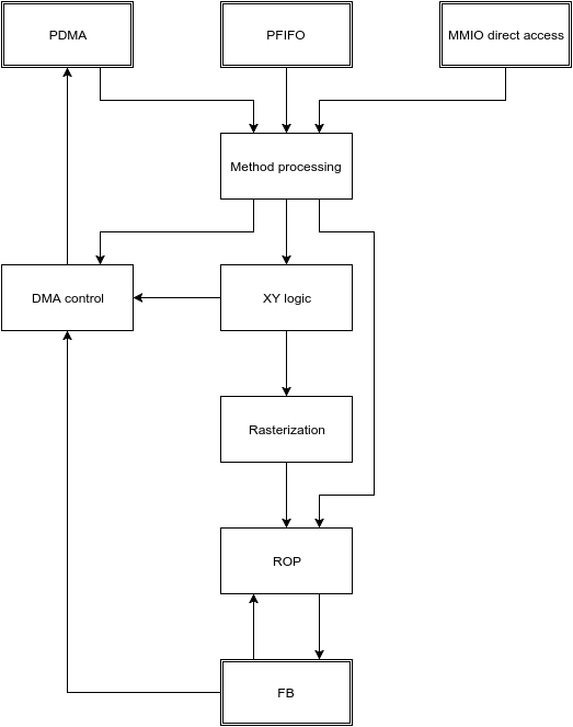
Most methods simply set some state in preparation for a subsequent drawing operation, and complete immediately. The remaining methods trigger some sort of operation involving the PGRAPH’s execution units:
- the XY logic unit, responsible for calculating the vertices of drawn primitives, and current position in case of IFC/BITMAP/IFM.
- the DMA control unit, sending read/write commands to PDMA and fetching framebuffer data for the ITM object.
- the rasterization unit, converting primitives to a series of pixels, and sending them to the ROP unit.
- the ROP unit, reading pixels from the framebuffer, performing per-pixel operations on them, and writing the results to the framebuffer.
5 different operations are supported:
- 2d draw: draws primitives according to the current object class. For POINT, LIN, LINE, TRI, RECT, and BLIT, the vertex data is sent from XY logic to the rasterizer and a single primitive is drawn. For IFC, BITMAP, and IFM, XY logic computes and emits a list of stripes to be drawn to the rasterizer.
- 3d draw: draws a few texels of a textured quad. XY logic computes and emits a list of triangles to be drawn to the rasterizer.
- image to memory: DMA control unit asks XY logic to walk through the pixels of a rectangle, reads their data from the framebuffer, and sends it to PDMA for writing to the DMA object.
- image from memory: DMA control unit submits read requests to PDMA, asking it to read from the DMA object and submit the data as payload of special draw-triggering methods back to PGRAPH. The incoming 2d draws from PDMA will be executed in parallel with this operation.
- notify: the PDMA unit is asked to write to the notify DMA object.
Todo
Lots of speculation here.
MMIO registers
-
8-bit spacenv1-pgraph[0x1000]¶ -
nv1-mmio0x400000: PGRAPH
Debug registers
These registers contain assorted flags controlling all sorts of graphics engine behavior.
-
reg32nv1-pgraph-debug-a¶ -
nv1-pgraph0x80: DEBUG_A - bit 0: RESET_TRIGGER - always reads as 0. Whenever written as 1, resets the graphics engine.
- bit 4: ???
- bit 8: ???
- bit 12: ???
- bit 16: ???
- bit 20: ???
- bit 24: ???
- bit 28: PLANE_ALPHA_ENABLE - if set, the plane mask alpha component will be used to discard pixels. Otherwise, it’ll be ignored.
Todo
lots of unknown bits
-
reg32nv1-pgraph-debug-b¶ -
nv1-pgraph0x84: DEBUG_B - bit 0: VOLATILE_RESET_LAST - whenever an object switch is performed, this is set to 1 if a volatile reset is performed, to 0 otherwise.
- bit 4: ??? - always reads as 0.
- bit 8: ???
- bit 12: ???
- bit 16: ???
- bit 20: ???
- bit 24: ???
- bit 28: ???
- bit 29: ???
Todo
lots of unknown bits
-
reg32nv1-pgraph-debug-c¶ -
nv1-pgraph0x88: DEBUG_C - bit 0: ???
- bit 4: ???
- bit 8: ???
- bit 12: ???
- bit 16: ???
- bit 20: ???
- bit 24: ???
- bit 28: ???
Todo
lots of unknown bits
Main control registers
-
reg32nv1-pgraph-ctx-switch¶ -
nv1-pgraph0x180: CTX_SWITCH - bits 0-15: OPTIONS - current object options,
- bits 16-22: CHID - current channel id (only valid if CHID_VALID
is set in
CTX_CONTROL, - bit 31: VOLATILE_RESET - set if the last object switch involved a volatile reset, performs no useful function on its own.
Any write to this register sets SWITCHING_BUSY in
CTX_CONTROLto 0, and VOLATILE_RESET_LAST inDEBUG_Bto 0 as well.
-
reg32nv1-pgraph-ctx-control¶ -
nv1-pgraph0x190: CTX_CONTROL bits 0-1: TIMER_BIT - controls the bit of PTIMER time monitored to determine timer expiration. One of:
- 0: bit 14 of time is monitored
- 1: bit 17
- 2: bit 20
- 3: bit 23
bit 8: TIMER_RUNNING - if set, the channel timeslice timer is running, and no channel switches should be done, to ensure a minimum channel timeslice. Otherwise, timeslice timer is expired. Whenever this is set to 1, it will auto-reset to 0 after the PTIMER time bit selected by TIMER_BIT changes 3 times.
bit 16: CHID_VALID - if set, the current channel id is considered valid. If not, it’s considered invalid, and activating an object will always trigger the context switch interrupt.
bit 20: SWITCH_AVAILABLE - read only, tells whether PGRAPH thinks now is a reasonable time to switch channels. Computed as follows:
- if DEVICE_ENABLED is 0, SWITCH_AVAILABLE is 0.
- otherwise, if CHID_VALID is 0, SWITCH_AVAILABLE is 1.
- otherwise, if at least one of SWITCHING_BUSY or TIMER_RUNNING is set, SWITCH_AVAILABLE is 0.
- otherwise, SWITCH_AVAILABLE is 1.
The value of this bit is exported to PFIFO.
bit 24: SWITCHING_BUSY - ???
bit 28: DEVICE_ENABLED - ???
Todo
Figure out what all that stuff does.
-
reg32nv1-pgraph-access¶ -
nv1-pgraph0x6a4: ACCESS - bit 0: FIFO - if set to 1, PFIFO is able to write to PGRAPH’s MMIO registers, ie. can submit methods. If set to 0, PFIFO method submission to PGRAPH will be blocked until it’s set back to 1.
- bit 4: DMA - if set to 1, PDMA is able to write to PGRAPH’s MMIO registers, ie. can respond to DMA read requests. If set to 0, PDMA read data will be blocked until it’s set back to 1. [XXX: verify]
- bit 8: HOST - if set to 1, the host is able to write to PGRAPH’s MMIO registers. If set to 0, writes to all registers in PGRAPH MMIO range from host will be ignored, except writes to ACCESS, INTR and INVALID registers. Reads to registers other than VTX_POS_* and VTX_BETA_* are unaffected.
- bits 12-16: OBJECT - the type of the current object. Automatically updated by PGRAPH when processing method 0. [XXX: what’s this for?]
- bit 24: FIFO_WR - when writing ACCESS and this bit is set to 1 in the written value, the FIFO field will be set as per the written value; when this bit is set to 0 in the written value, the FIFO field will be unaffected. When reading ACCESS, always reads as 1. This, together with the following 3 bits, can be used to selectively write ACCESS bitfields.
- bit 25: DMA_WR - like FIFO_WR, but for DMA field
- bit 26: HOST_WR - like FIFO_WR, but for HOST field
- bit 27: OBJECT_WR - like FIFO_WR, but for OBJECT field
Note that the FIFO and HOST bits will be automatically cleared by PGRAPH when an interrupt is triggered by execution of a method. The host has to reenable HOST access in the interrupt handler to manipulate any PGRAPH state.
The last submitted method can be read from a pair of registers:
-
reg32nv1-pgraph-trap-addr¶ -
nv1-pgraph0x6a8: TRAP_ADDR This is a read-only register containing the address of the last submitted method.
Todo
bitfields
-
reg32nv1-pgraph-trap-data¶ -
nv1-pgraph0x6ac: TRAP_DATA This is a read-only register containing the data payload of the last submitted method.
The current busy status of PGRAPH can be checked by reading the STATUS register:
-
reg32nv1-pgraph-status¶ -
nv1-pgraph0x6b0: STATUS A read-only register that can be used to determine what PGRAPH is doing at the moment.
- bit 0: BUSY - PGRAPH is busy processing some method (always set if any other bit is set)
- bit 4: XY_LOGIC - PGRAPH is busy calculating vertex coordinates
- bit 16: DMA - PGRAPH is busy talking to PDMA about IFM or ITM DMA
- bit 20: DMA_NOTIFY - PGRAPH is busy talking to PDMA about NOTIFY DMA
Todo
more bits
Interrupts
The PGRAPH registers dealing with interrupts are:
-
reg32nv1-pgraph-intr¶ -
nv1-pgraph0x100: INTR -
nv3-pgraph0x100: INTR Status of interrupts generated by PGRAPH. On read, returns 1 for bits corresponding to pending interrupts. On write, if 1 is written to a bit, its interrupt gets cleared, if 0 is written nothing happens.
- bit 0: INVALID - something was wrong with the submitted method. Detailed status is available in the INVALID register. Clearing this bit will also clear the INVALID register. In turn, clearing the INVALID register will clear this bit.
- bit 4: CONTEXT_SWITCH - a CTX_SWITCH method was submitted and the channel id and/or SUBCONTEXT_ID is different from the current one.
- bit 8: VBLANK - the vertical blanking period has started on PFB. This is really PFB’s interrupt. It is delivered to a different PMC line than other PGRAPH interrupts. See NV1 PFB for details.
- bit 12: XY_RANGE - an X or Y coordinate used for rendering was out of the -0x8000..0x7fff range supported by the rasterizer
- bit 16: MISSING_METHOD - the final method to do an operation was submitted without first submitting other required methods
- bit 20: CANVAS_SOFTWARE - a drawing operation was attempted with SOFTWARE bit set in CANVAS_CONFIG.
- bit 24: CLIP_SOFTWARE - a drawing operation was attempted with SOFTWARE bit set in CLIPRECT_CTRL.
- bit 28: NOTIFY - a method on which notify interrupt was requested has been executed
-
reg32nv1-pgraph-intr-en¶ -
nv1-pgraph0x140: INTR_EN -
nv3-pgraph0x140: INTR_EN Interrupt enable bitmask. Set to enable, clear to disable. Interrupts that are masked will still show up in INTR when they’re triggered, but won’t cause the PGRAPH or PFB interrupt line to go active. Has same bitfields as INTR.
Interrupts other than VBLANK are delivered to PMC interrupt line 12. VBLANK interrupt is delivered to PMC interrupt line 24.
The INVALID interrupt is further controlled by these registers:
-
reg32nv1-pgraph-invalid¶ -
nv1-pgraph0x104: INVALID -
nv3-pgraph0x104: INVALID Status of INVALID subinterrupts. Works like INTR. Clearing this register will also clear the INVALID bit in INTR register. In turn, clearing INVALID bit in INTR will also clear this register.
- bit 0: INVALID_METHOD - the method that was submitted does not exist
- bit 4: INVALID_VALUE - the method was submitted with invalid parameter
- bit 8: INVALID_NOTIFY - a NOTIFY method was submitted, but NOTIFY_VALID was not set in graph object options
- bit 12: DOUBLE_NOTIFY - a NOTIFY method was submitted with NOTIFY_PENDING already set
- bit 16: CTXSW_NOTIFY - a CTX_SWITCH method was submitted with NOTIFY_PENDING set
-
reg32nv1-pgraph-invalid-en¶ -
nv1-pgraph0x144: INVALID_EN -
nv3-pgraph0x144: INVALID_EN INVALID interrupt enable bitmask. Set to enable, clear to disable. Same bitfields as INVALID. If any interrupt active in INVALID is also enabled here, interrupt line to PMC will be active. Note that this register does not affect triggering the INVALID bit in INTR and the interrupt status from INTR&INTR_EN will be effectively ORed with INVALID&INVALID_EN. Thus the contents of INVALID_EN will only matter when INTR_EN.INVALID is set to 0.
The INTR and INVALID registers are special and can be written by host even if ACCESS.HOST is not set.
Note that interrupts that are disabled will still cause PGRAPH to halt and disable FIFO/HOST bits in ACCESS.
Classes and their methods
-
8-bit spacenv1-ubeta[0x10000]¶ -
nv1-mmio0x410000: UBETA This class exists only to set the global blending factor, used by objects with operation set to BLEND_*. It uses no special options.
Address Name Description 0x0 OBJECT Object switch 0x104 NOTIFY Notification request 0x300 BETA Set the beta blending factor
-
8-bit spacenv1-urop[0x10000]¶ -
nv1-mmio0x420000: UROP This class exists only to set the global bitwise operation, used by objects with operation set to ROP_* and PROP_*. It uses no special options.
Address Name Description 0x0 OBJECT Object switch 0x104 NOTIFY Notification request 0x300 ROP Set the bitwise operation
-
8-bit spacenv1-uchroma[0x10000]¶ -
nv1-mmio0x430000: UCHROMA This class exists only to set the global color key, used by objects with CHROMA enabled in their options. It uses the color format part of COLOR_FORMAT_DST option itself.
Address Name Description 0x0 OBJECT Object switch 0x104 NOTIFY Notification request 0x304 CHROMA Set the color key
-
8-bit spacenv1-uplane[0x10000]¶ -
nv1-mmio0x440000: UPLANE This class exists only to set the global plane mask, used by objects with PLANE enabled in their options. It uses the color format part of COLOR_FORMAT_DST option itself.
Address Name Description 0x0 OBJECT Object switch 0x104 NOTIFY Notification request 0x304 PLANE Set the plane mask
-
8-bit spacenv1-upattern[0x10000]¶ -
nv1-mmio0x460000: UPATTERN This class exists only to set the global pattern, used by objects with operation set to ROP_*P*, or BLEND_PS_*. It uses the color format part of COLOR_FORMAT_DST option, and the BITMAP_FORMAT option itself.
Address Name Description 0x0 OBJECT Object switch 0x104 NOTIFY Notification request 0x308 PATTERN_SHAPE Set pattern shape 0x310+i*0x4 (i<2) PATTERN_BITMAP_COLOR[i] Set pattern bitmap color 0x318+i*0x4 (i<2) PATTERN_BITMAP[i] Set pattern bitmap
Todo
write me
The object switch method
-
reg32nv1-mthd-gr-object¶ -
nv1-ubeta0x0: OBJECT -
nv1-urop0x0: OBJECT -
nv1-uchroma0x0: OBJECT -
nv1-uplane0x0: OBJECT -
nv1-upattern0x0: OBJECT Todo
write me
DMA operation
Todo
write me
Surface setup
Todo
write me
Drawing operation
Todo
write me